Philips Semiconductors Product specification
Rectifier diodes BYV72EW series
ultrafast, rugged
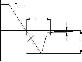
Fig.1. Definition of trr1, Qs
and I
rrm
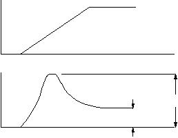
Fig.2. Definition of Vfr
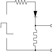
Fig.3. Circuit schematic for trr2
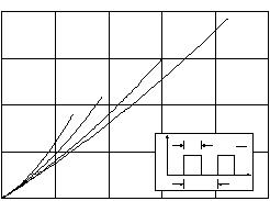
Fig.4. Definition of trr2
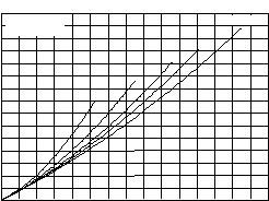
Fig.5. Maximum forward dissipation PF
= f(I
F(AV)) per
diode; square current waveform where
IF(AV)
=I
F(RMS)
x
√D.
Fig.6. Maximum forward dissipation PF
= f(I
F(AV)) per
diode; sinusoidal current waveform where a = form
factor = IF(RMS)
/ I
F(AV).
Q
s
100%
10%
time
dI
F
dt
IR
I
F
Irrm
trr
I = 1AR
I = 0.25Arec
0A
trr2
0.5A
IF
IR
time
time
V
F
V
fr
V
F
I
F
00 5 10 15 20 25150
5
10
15
20
PF / W
Vo = 0.705 V
0.5
0.2
0.1
BYV42
IF(AV) / A
D = 1.0
Tmb(max) / C102
138
126
114
Rs = 0.0097 Ohms
D = tpT
tp
T
t
I
shunt
Current
to 'scope
D.U.T.
Voltage Pulse Source
R
0
150
0 5 10 15
IF(AV) / A
5
10
15
PF / W
Vo = 0.705 V
1.9
2.2
2.8
4
BYV42
Tmb(max) / C
a = 1.57
114
138
126
Rs = 0.0097 Ohms
October 1998 3 Rev 1.200


发布紧急采购,3分钟左右您将得到回复。
相关PDF资料
BYV74W-400,127
DIODE RECT 400V 30A SOT429
BYW51-200G
DIODE ULT FAST 200V 8A TO-220AB
C-20-0403F
VFD CUSTOM DVD DISP 7MM
C-20-0503F
VFD CUSTOM DVD DISP 5.8MM
C-20-0902
VFD CUSTOM AUDIO DISP15.5MM
C-20-1003FN
DISPLAY VFD CUST AUDIO
C-20-1301
VFD CUSTOM DVD DISP 7MM
C-22-0501NA
DISPLAY VFD CUST AUDIO
相关代理商/技术参数
BYV72EW-200
制造商:NXP Semiconductors 功能描述:DIODE ULTRA FAST 2X15A
BYV72EW-200/B
制造商:未知厂家 制造商全称:未知厂家 功能描述:DIODE EPITAXIAL
BYV72EWSERIES
制造商:PHILIPS 制造商全称:NXP Semiconductors 功能描述:Rectifier diodes ultrafast. rugged
BYV72F
制造商:PHILIPS 制造商全称:NXP Semiconductors 功能描述:Rectifier diodes ultrafast
BYV72F-100
制造商:PHILIPS 制造商全称:NXP Semiconductors 功能描述:Rectifier diodes ultrafast
BYV72F-150
制造商:PHILIPS 制造商全称:NXP Semiconductors 功能描述:Rectifier diodes ultrafast
BYV72F-200
制造商:PHILIPS 制造商全称:NXP Semiconductors 功能描述:Rectifier diodes ultrafast
BYV74
制造商:PHILIPS 制造商全称:NXP Semiconductors 功能描述:Dual rectifier diodes ultrafast
